I got the HP 1607A, which was previously non-functional, up and running!
I opened up the machine today and poked around looking for faults in a power rail, but upon first look every rail seemed ok. The voltage rails +5v, +12v, and -12v all looked fine.
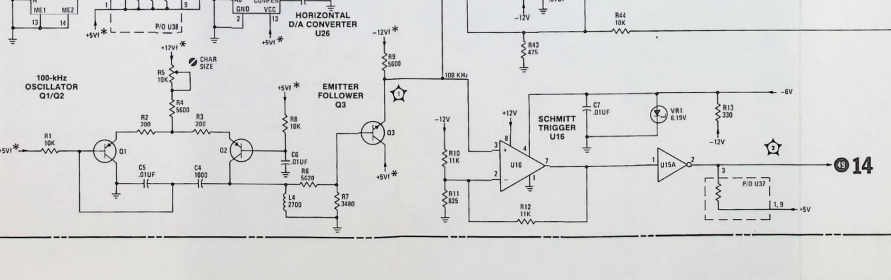
The next step was to understand why the Z-blanking signal which is output at the rear of the machine was missing… I spent the next fifteen minutes or so tracking backwards until I found the source of the problem which was a missing 100 khz clock. The issue was some issue in this circuit:
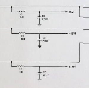
It turns out that 5Vf was missing. I tracked it back to an earlier schematic page and it appears to be sourced from an inductor.
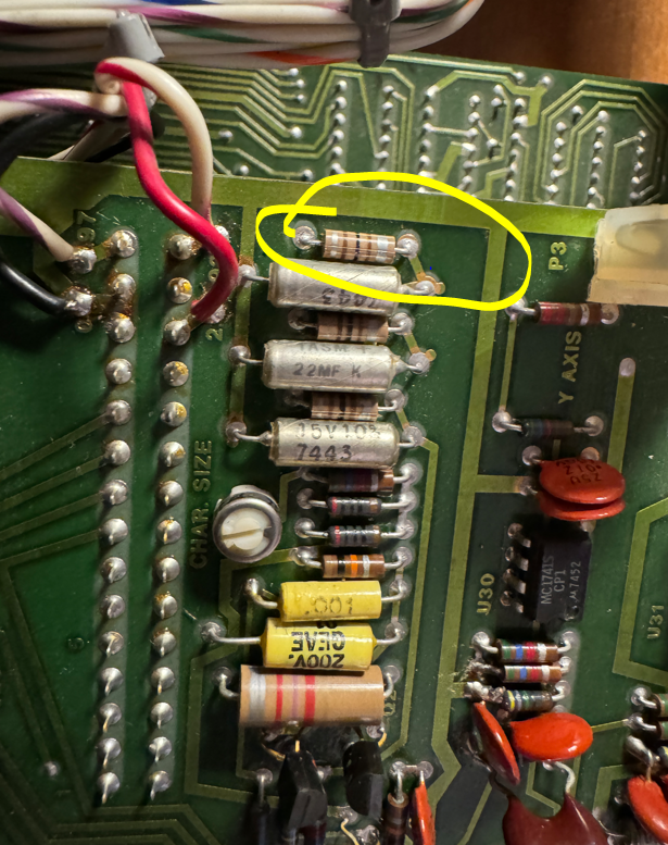
I grabbed my soldering iron and swapped this guy out…
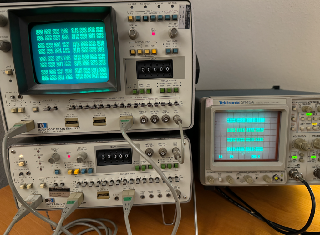
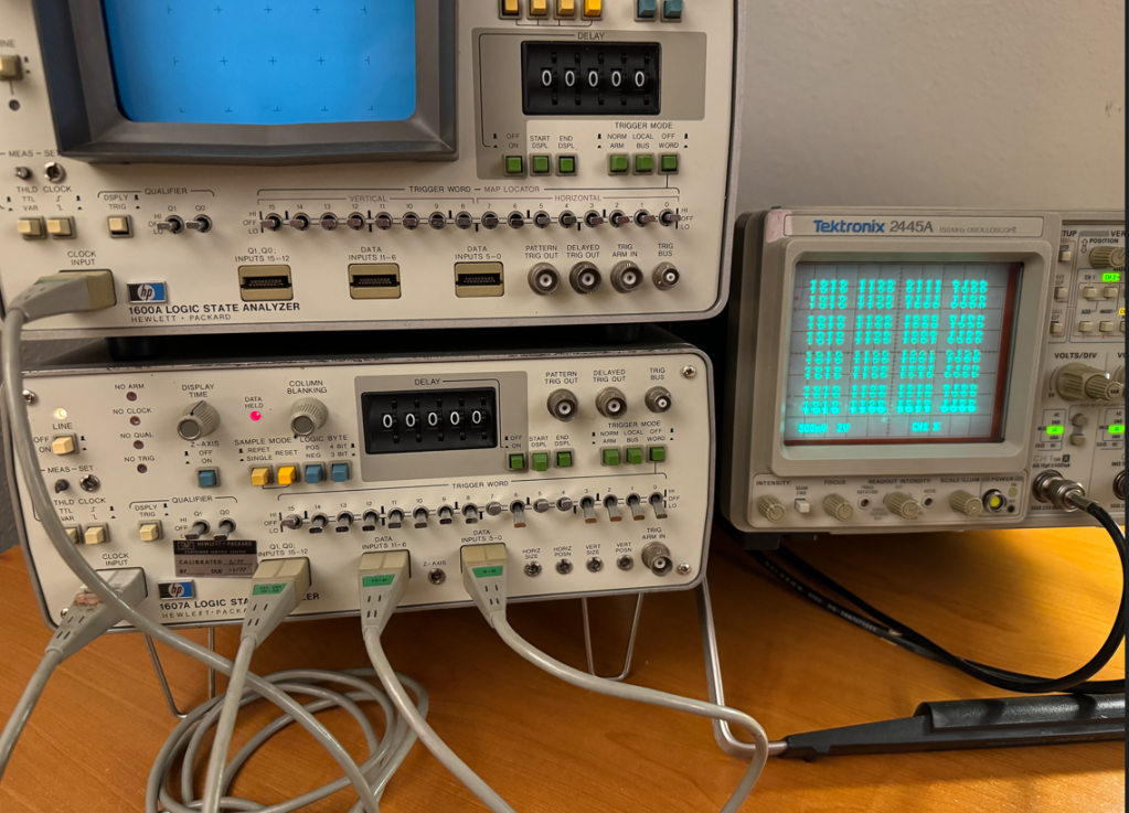
I picked up a vintage HP 1600A/1607A logic analyzer set over the weekend which was state of the art back in 1975. I thought I would see if I could at least get them running and functional and then maybe develop some interesting stunt!
I was surprised that the 1600A was able to power up and render anything onto the display considering the fifty year old caps could be totally dried out by now and kept the power supply from working… The buttons were a bit sticky but none appeared broken.
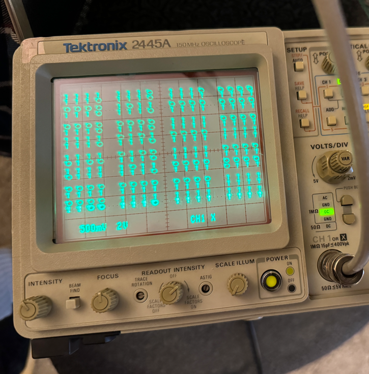
The HP 1607A, however, was not able to send a sync signal on the Z channel, so in this case I do think there is an issue with its power supply likely due to dry caps. I will debug this machine some other time…
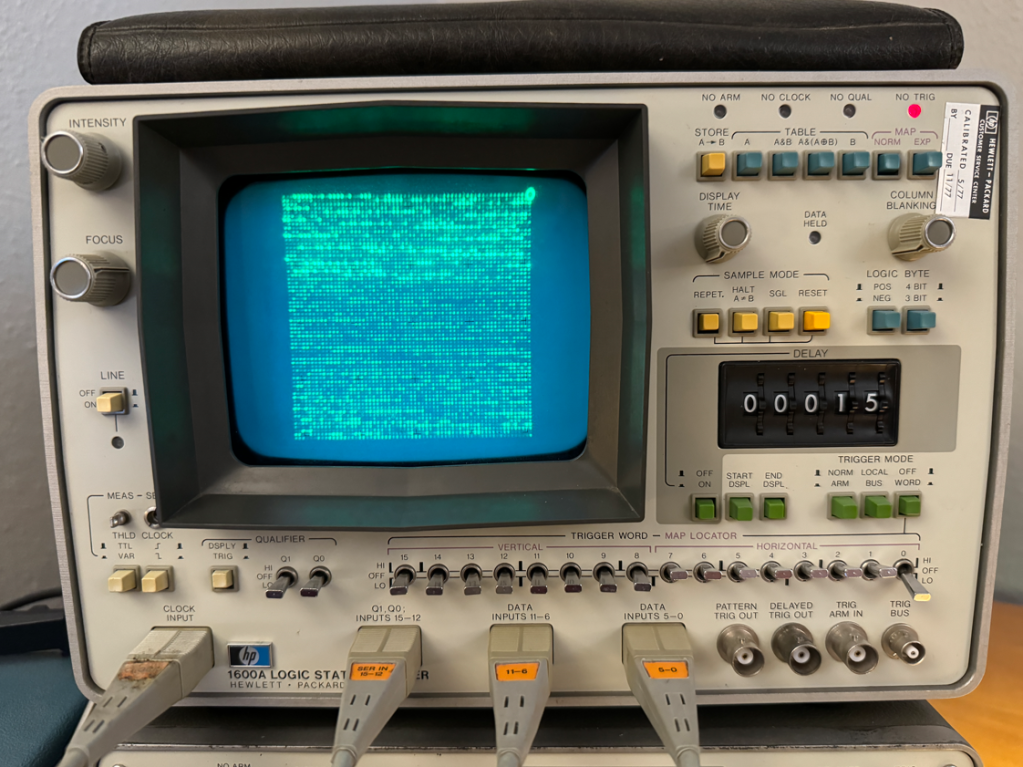
Since the HP1600A is a logic analyzer, the logical next step to test it would be to develop a way to generate stimulus, so I decided to employ a Teensy 4.1 to provide 32 data signals and two clock outputs. I whipped up some code and had a nice pattern on the analyzer in no time. One thing I found interesting was that when this unit is used as stand-alone, the 16 channels are justified to the left…
This was fun for about two minutes, so I began to look for a way to make this analyzer do something more interesting…
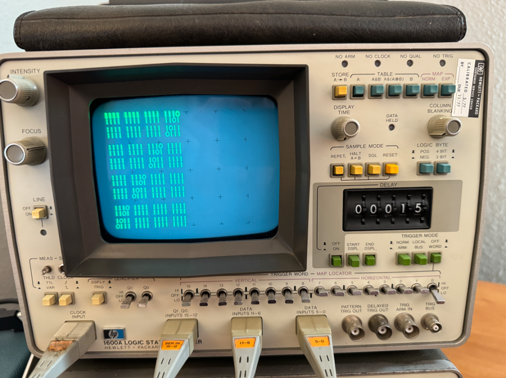
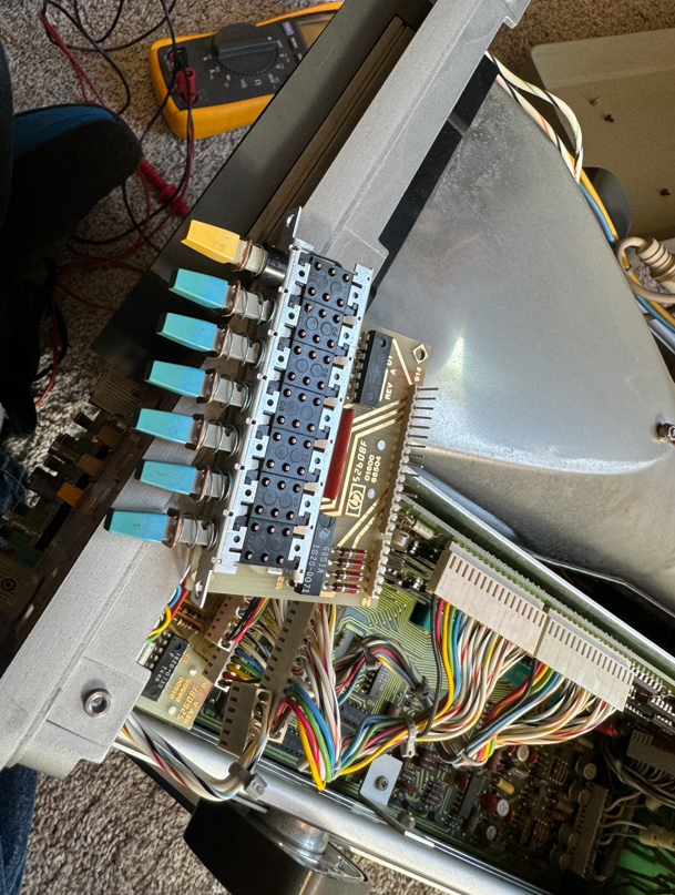
This analyzer also has a “MAP” function which is basically an addressable X-Y mode that allows the user to write to any of the display’s 64×64 pixels. This is enabled with the MAP switch at the top right. but it was not operating consistently due to the stickiness, so I had to take the machine apart to use contact cleaner on all of the switches and dials that I could reach.
Here is the offending switch which I doused with contact cleaner:
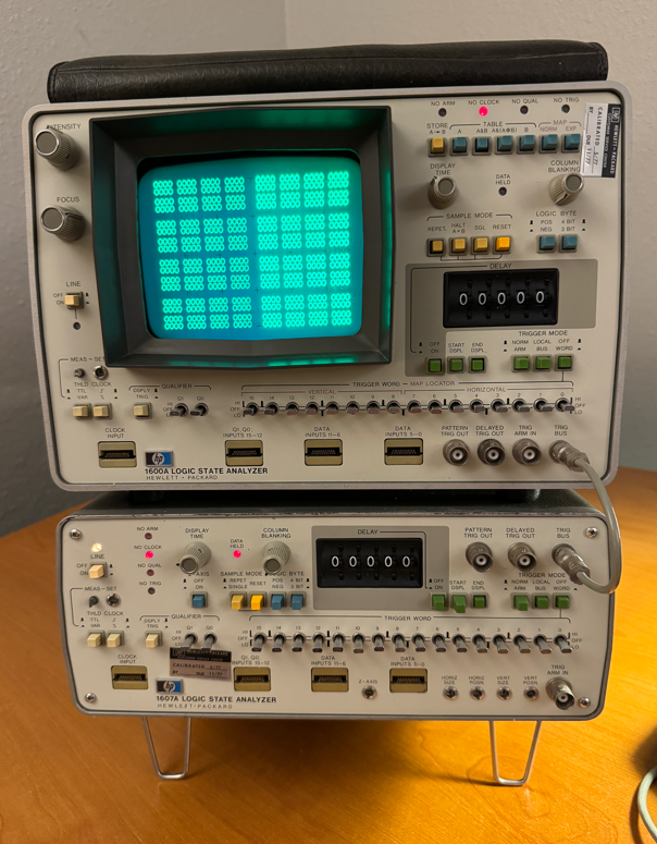
Once the machine was reassembled, MAP mode worked fine, so I made a small program to write pixels in random locations all around the screen which was much more interesting than walking-bit number paterns!
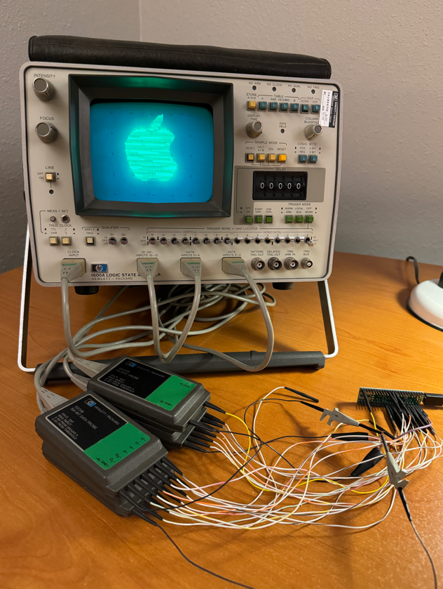
The next step after that was to try sending images to the display. The best way I know to do this is by using images stored in BMP format which, for B&W images has either a 0 ot 1 for each pixel in the image.
I used GIMP to resize and export the images to a BMP file and made a small C program to convert and send the 64×64 image to the format used by the logic analyzer’s MAP mode to display on the screen.
When seen in real life the image has a very pleasant shimmers. Im guessing it may be because I am sending screen refreshes faster than the machine expects or was designed to handle, but is any case it looks nice… 🙂
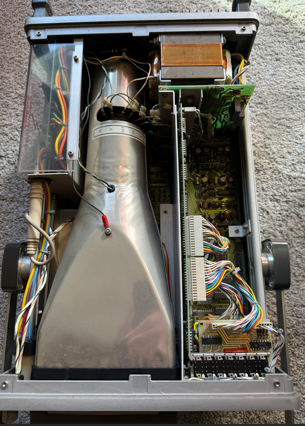
The next step will be to crack open and debug the HP 1607A, but that’s a project for another day!
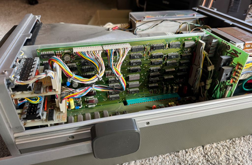
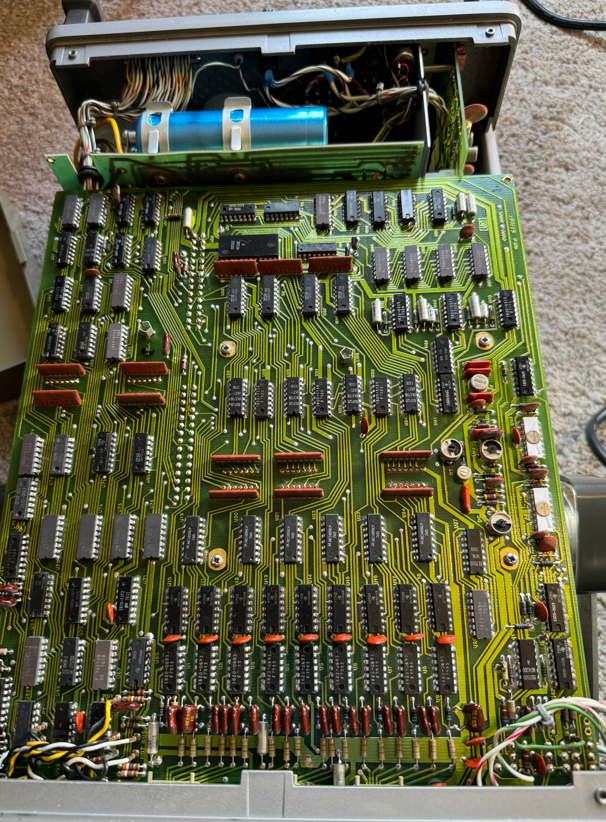
Here are a few more pictures of the insides of the HP 1600A:
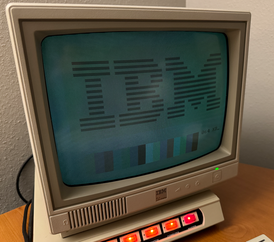
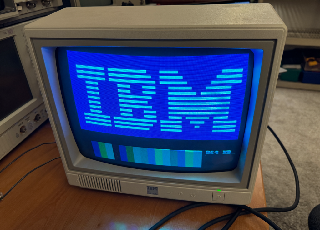
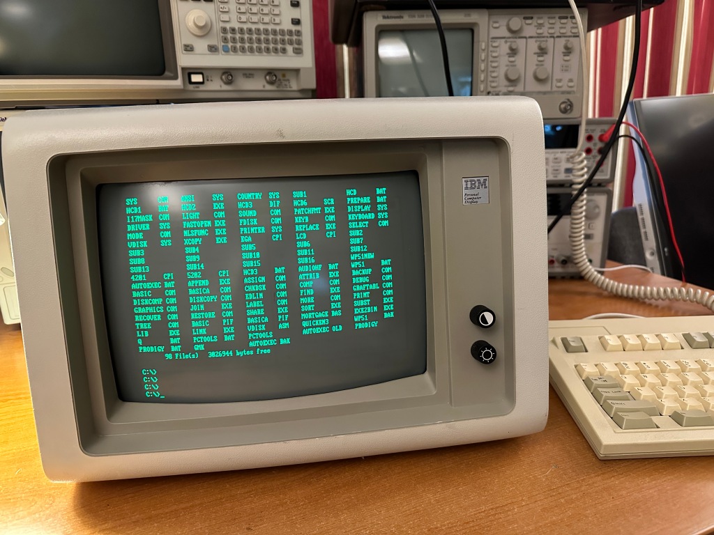
I took my IBM PCjr and its display out of storage, powered it up, and encountered this:
It appeared to be missing some colors – mainly blue.
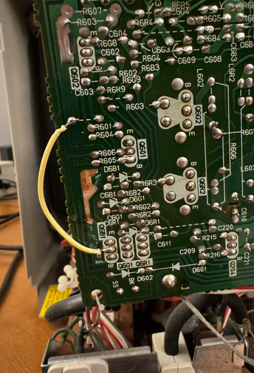
I took the display apart and removed a metal shield from the neck-board. When I powered up the display there was nothing displayed! It took me a few minutes to realize that I had ripped off a trace which was soldered to the metal shield. I should have been more careful, but it was an easy fix…
Thanks to a user on the VCF web-site I was able to isolate the fault to a short in one of the capacitors on the neck board. I snipped one of the capacitor’s legs and the colors immediately returned! I replaced the cap and put the display back together. A quick fix thanks for the VCF community!
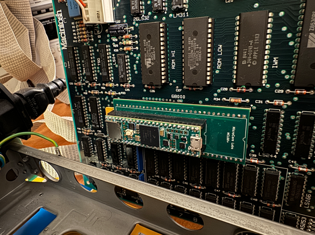
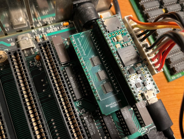
The MCL68+ is a Motorola 68000 drop-in replacement emulator. It uses the Teensy 4.1 to emulate both the microprocessor and the local bus interface at full speed. It is the most ambitious drop-in emulator I have designed to date, and I am pleased with the progress I was able to achieve.
Below is a picture of the MCL68+ inside of a Macintosh 512K – the “Fat Mac” It is able to emulate a cycle-accurate 68000 and successfully run the local bus interface at the full 7.8 Mhz bus speed. This is the fastest bit-banged local bus speed that I have ever achieved using a Teensy 4.1! It required a number of tricks such as pre-calculating addresses and using arrays to map GPIO values to the Teensy’s output registers. The Motorola 68000 also required more pins than were available on the Teensy 4.1, so I used a series of byte-wide latches to shift out the address and data busses.
Here is a short video which demonstrates the MCL68+ booting System 2 on the Macintosh 512K. The progress always stops here, but I am able to move the cursor around with the mouse and reboot the machine, so the system is not locked up. I traced the error to an attempted subroutine jump to a misaligned address, but I have not had the time to trace the code backwards to find where this address comes from. Still, the fact that it performs the system configuration and checks and then boots from the disk drive indicates that most of the MCL68+ emulation is correct. Im not sure at this point is there is a problem with my emulation of some opcode, or some quirk with the Macintosh hardware which I am not accommodating…
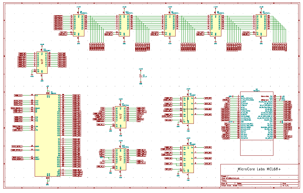
The Teensy did not have enough GPIOs to implement each of the 68000’s actual pins, so to get all 24 bits of the address bus and 16 bits of the data bus I use a byte-wide shift register using a series of five 74HCT574’s I also needed to multiplex a few other signals to squeeze it all onto the Teensy’s pins.
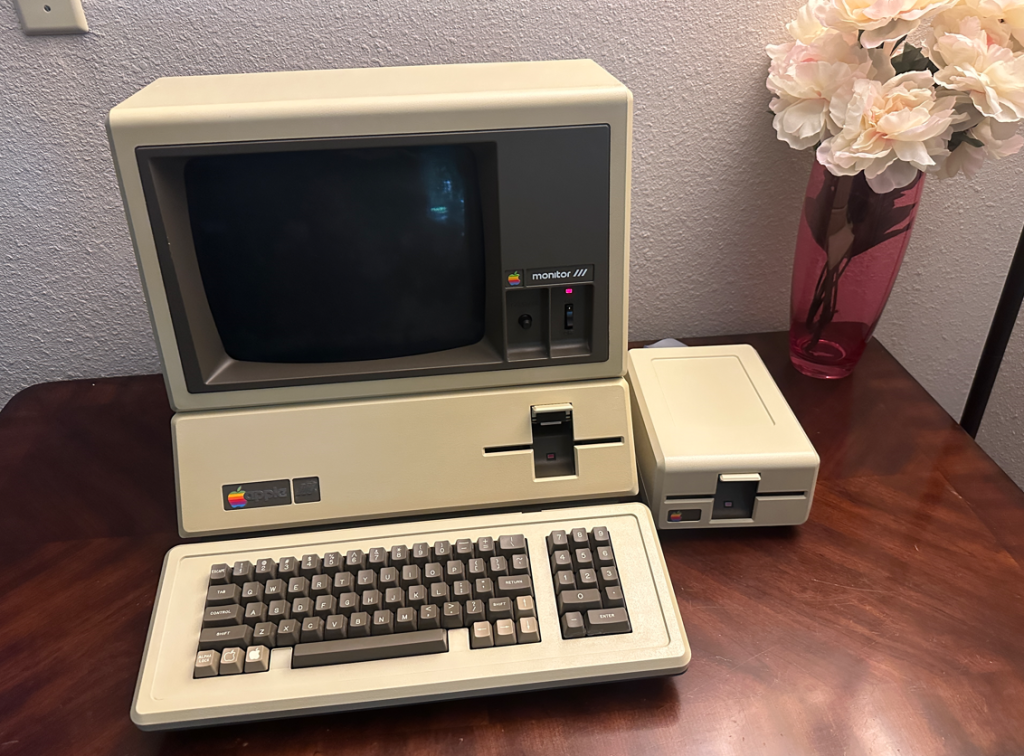
I recently acquired an Apple III which was not able to boot so I thought it would be a good opportunity to drop-in my MCL65+ to replace the 6502 to help debug the motherboard. It is a beautiful machine which included the Apple III monitor and an external disk drive. It is the first model which contains a 12V memory card.
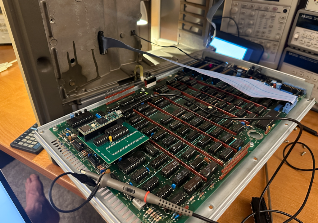
I wrote some code to have the MCL65+ perform an infinite read loop from ROM address 0xFFFF which should have resulted in activity on the ROM’s chip select line but did not.
Starting at the ROM, I traced the net back through every IC in the path, back to the source which ended up being an Apple PLD. It appeared to have a bad output driver which could drive to a logic ‘1’ but not to a ‘0’.
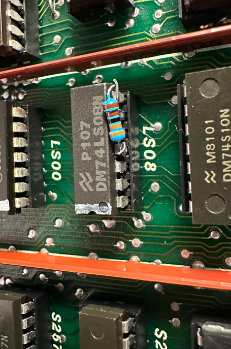
I added a 680 ohm pulldown to this signal help the chip bring the voltage level to zero which seemed to work quite well. The machine was then able to boot from the ROM and begin trying to load the OS from the disk drive. It was a step in the right direction but the machine could still not load the SOS operating system.
This is the resistor which I placed at the input of the AND gate:
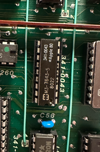
And this is the source IC which is an Apple PLD. The chip was extremely hot, but I’m not sure if it was because the chip is damaged or if it is always this hot. Many of the other Apple PLDs are also hot…
It is my understanding that the Apple III will operate at a clock speed of 2 Mhz when accessing some address ranges and 1 Mhz for others, so I worry that my 680 ohm pulldown solution may not work at the faster clock speed. I looked over the schematic for a way to force the motherboard to run full-time at 1 Mhz.
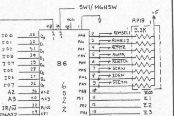
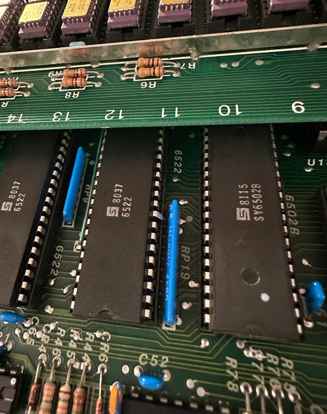
The solution was to bend pin-9 of the 6522 so that it no longer can drive the signal SEL2M_n low which switches the clock speed. With this pin disconnected the pull-up on the signal should keep the speed always at 1 Mhz.
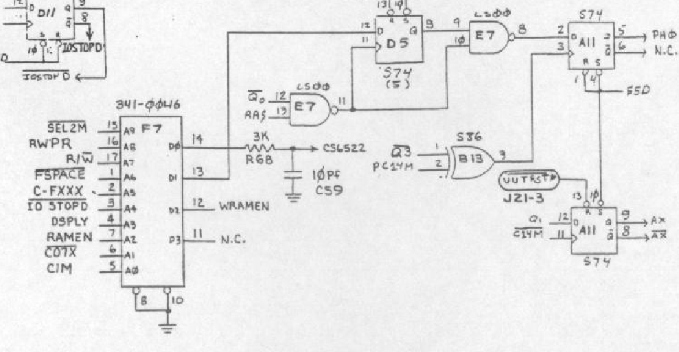
This is the circuit from the schematic. SEL2M_n is sourced by the 6522 and goes into an Apple PLD which then controls the ability of the system to run at 2 Mhz depending on which address is being accessed.
With the motherboard clock speed fixed to 1 Mhz it makes this the world’s slowest Apple III. 🙂
I dont think this will cause any compatibility issues because my observation was that anytime the CPU access I/O such as the disk drive, the machine would switch to 1 Mhz. I think it only runs at 2 Mhz when the CPU is executing out of memory.
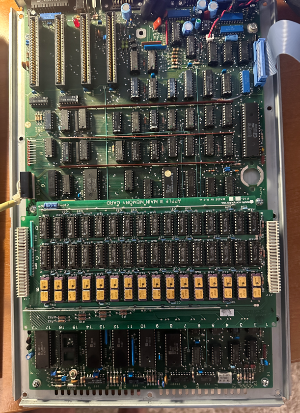
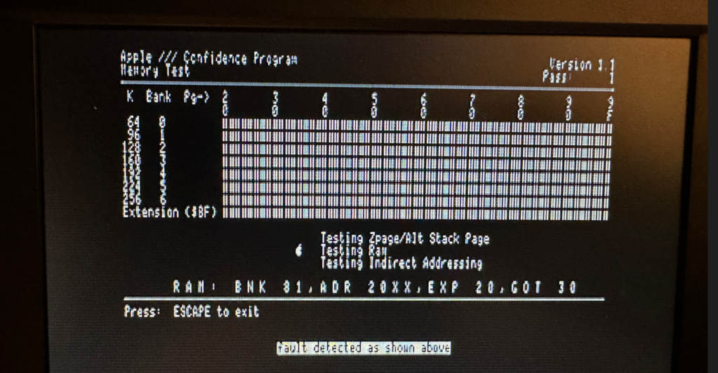
I ran the Apple III Confidence memory test program which helped me locate a few bad DRAMS on the 12V memory board which I replaced with chips donated from my Apple II+.
After this, the machine appears to be fixed! It can boot SOS and I can run a number of other applications. The computer is a bit slower than stock but I believe it is a worthwhile tradeoff if the motherboard ICs will run cooler and extend their lives.
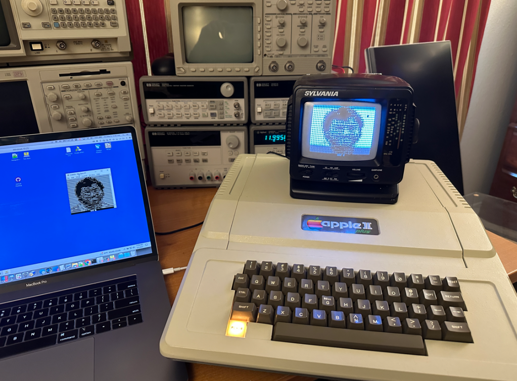
The MCL65+ is a drop-in replacement the computer’s MOS 6502 which can emulate the microprocessor and much more.
The Apple II BIOS is replaced by the Woz’s Monitor, so the machine is quite effectively running as an Apple 1.
The MCL65+ uses a Teensy 4.1 to emulate the 6502, the Apple I PROMs which contain the famous 256 byte Woz Monitor, 8 KB of RAM, and a few conversion routines for differences in video display and keyboard handling,
All keyboard and video I/O are also echoed to the Teensy’s UART so that code could be downloaded to the Apple 1 by simply cutting and pasting it into a terminal program.
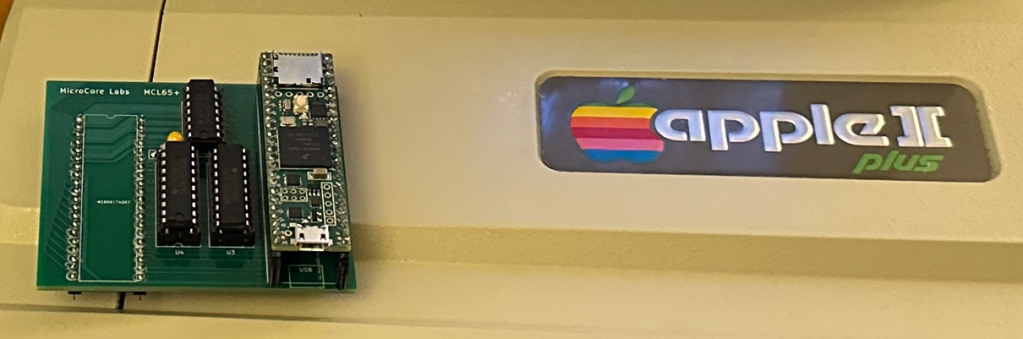
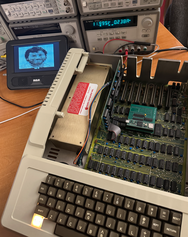
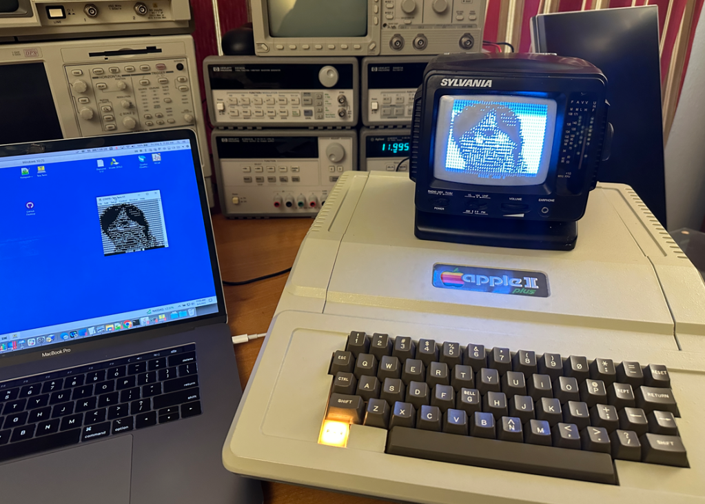
Here is the MCL65+ inside of the Apple II Plus:
Here is a short video demonstration of the project:
To save time I pre-populated BASIC into memory location 0xE000 and also the Apple I anniversary program into 0x0280.
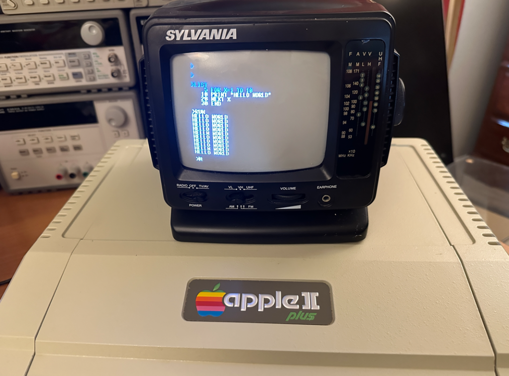
Here is a short BASIC programs which I downloaded over the UART:
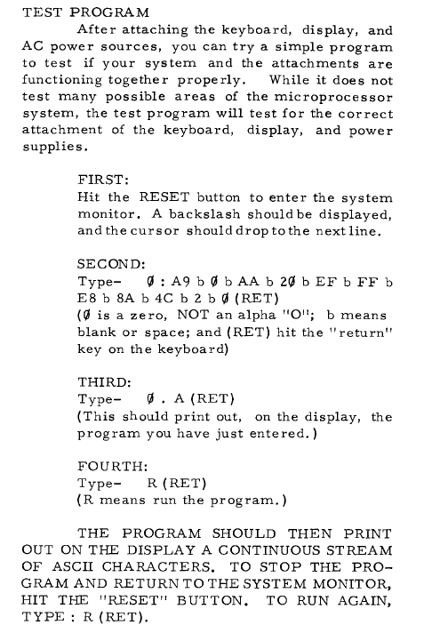
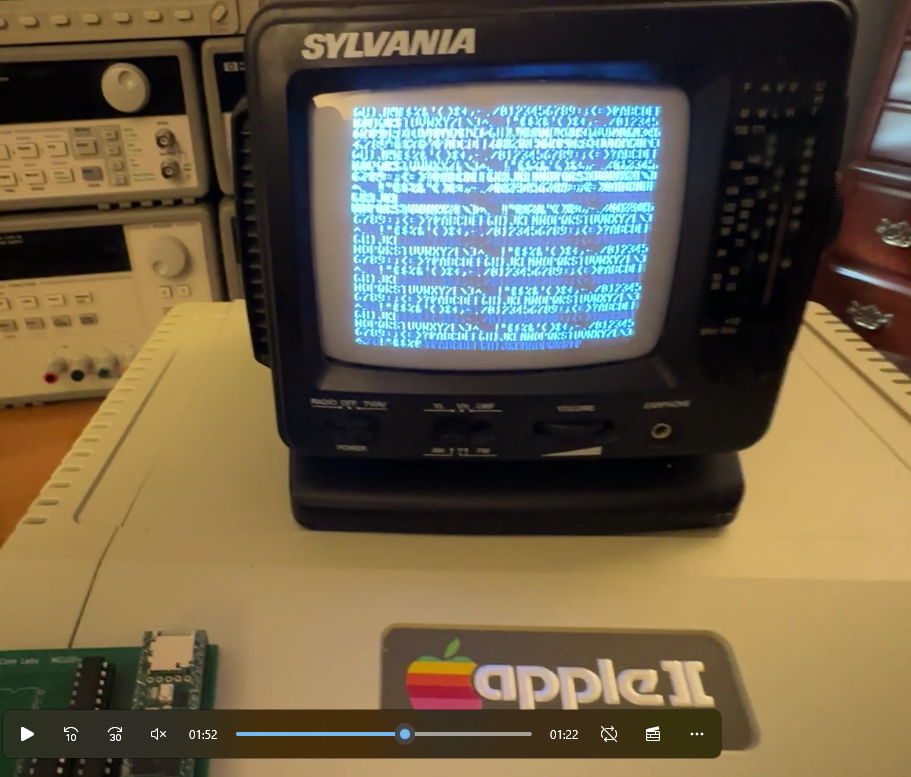
The Apple I Operation Manual contained a small program to print ASCII character across the screen, so of course this was the first thing I tried when bringing the system up!
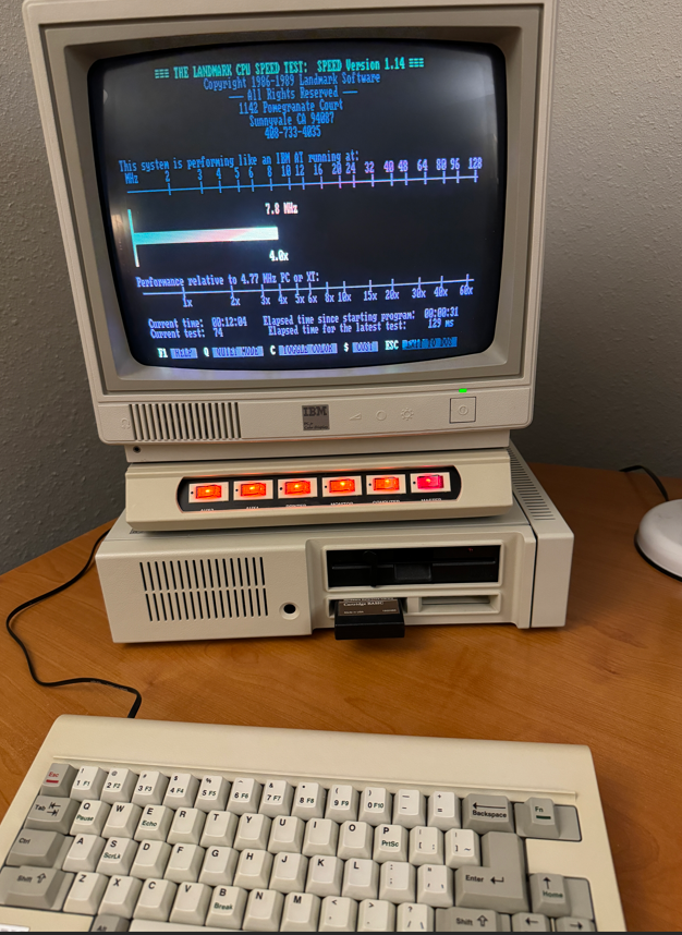
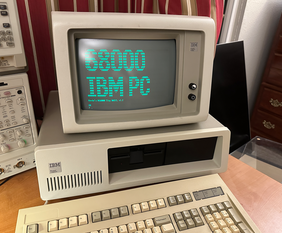
I was wondering what the IBM Personal Computer would have been like if they had chosen the Motorola 68000 instead of the Intel 8088, so I used my MCL86+ to emulate the 68000 and find out!
The MCL86+ is a board which uses a Teensy 4.1 to emulate a microprocessor in C code as well as use its GPIOs to emulate the local bus of the Intel 8088. It can be used as a drop-in replacement for the Intel 8088 and can be cycle accurate as well as run in accelerated modes.
For this project I swapped the 8088 emulation code with my MCL68 code which emulates the Motorola 68000. The 8088 local bus emulation was kept so that all of the 68000’s memory reads and writes could pass through to the IBM motherboard.
Emulating the 68000 is fine, but not very useful without an operating system or some other application to run on it. I chose to use Gordon Brandley’s 68K BASIC which was published in Dr. Dobbs Journal back in 1985.
I should note that just the 68000 emulation is running inside of the MCL86+. All of the IBM motherboard peripherals, video, and memory are used for this project. Video is drawn to the IBM MDA card’s video memory over the ISA bus. BASIC is run out of 64 KB of the motherboard DRAM which is refreshed by the 8327 DMA controller by an interval set by the 8253. The keyboard receives the serial data and generates an interrupt through the 8259 and is cleared by accesses to the 8255. Basically all of the major components and glue logic of the IBM motherboard are used!
I ran a few tests and it seems that there is not much of a performance difference between running an 8088 and a 68000 on the IBM motherboard which uses 8-bit chips exclusively. If IBM had chosen the 68000 they may actually have used the 68008 which is a 68000 with an 8-bit local bus interface. Perhaps this chip was not available at the time IBM’s project, code-named ‘Chess’, was in development. It could also have been the case that Microsoft did not have an operating system or BASIC ported to the Motorola 68000 architecture. What this project shows is that the performance difference was not so profound that it would have made a difference in IBM’s selection process.
Here are some videos of the machine in action:
I hope this project helped satisfy those who have wondered what the IBM Personal Computer would have been like if they had selected the Motorola 68000 instead of the Intel 8088!
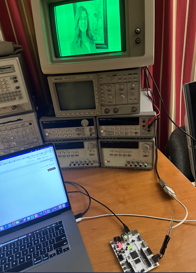
I am using a Digilent Arty Z7-20 SOC FPGA development board which contains a 600 Mhz ARM processor and has access to 500 MB of DRAM.
The FPGA core contains a 720-bit wide dual-ported RAM and a small state machine to fetch each display row and generate the MDA display timing.
Images are held in an array in the C code running on the ARM core which is then copied down to the dual-ported RAM in the FPGA code. This makes it easier to reload new images rather than storing the images in the FPGA core’s configuration bitstream.
The image array holds the full 720×350 bit image with one bit per pixel . It is generated by using GIMP to convert the original JPEG image to the appropriate size and color, then save as a BMP image. This image file is then converted to an array using a small C program I wrote.
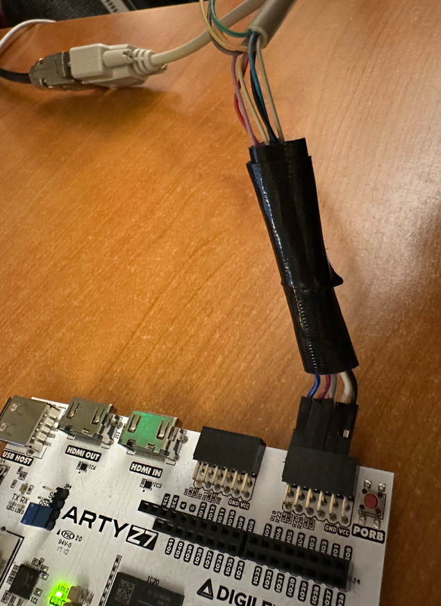
I made this small cable to connect the MDA signals to the FPGA’s PMOD connector inputs.
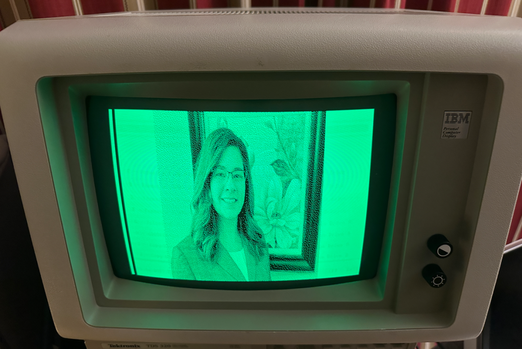
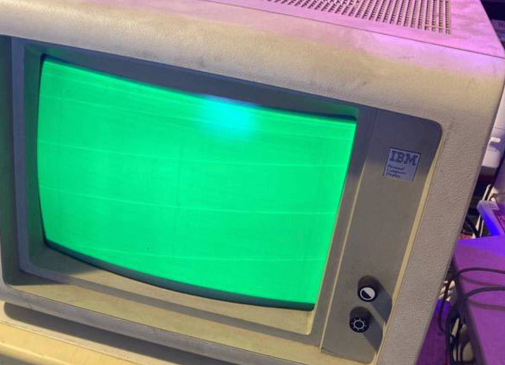
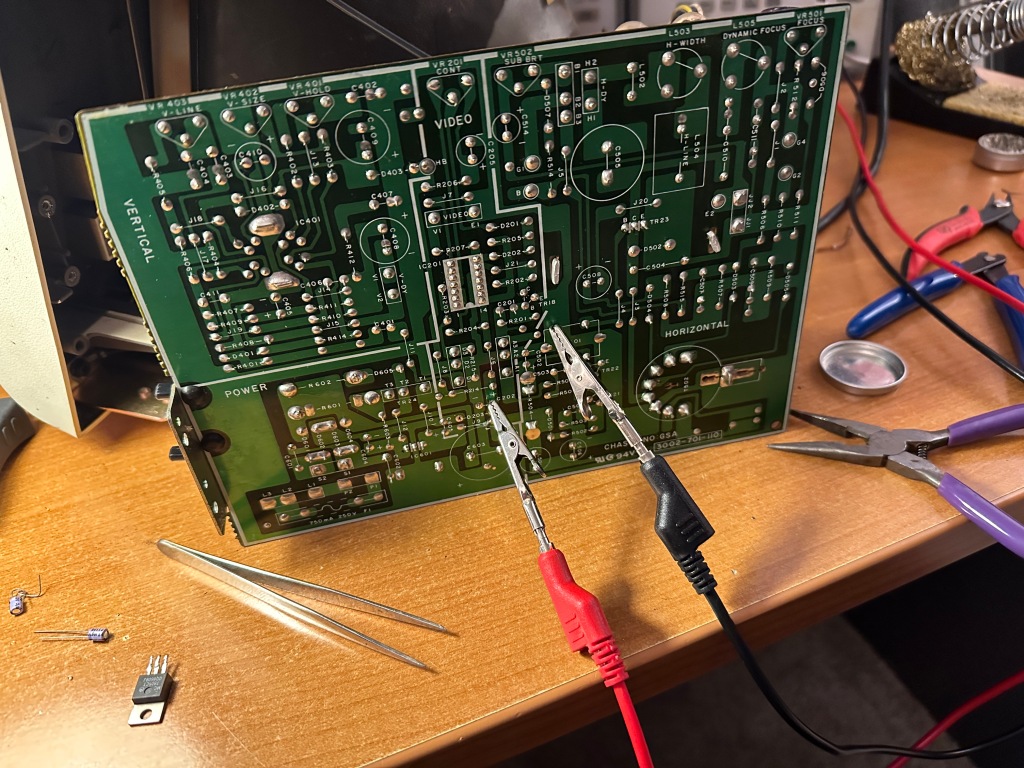
I came into possession of an IBM 5151 MDA monitor which was in rough and non-functional condition. There was a raster on the screen but no video. My sense was that most of the circuitry was working and that the problem would be with something small-signal or digital as opposed to related to a high-voltage circuit.
After probing the power rails I found that the +5V was missing.
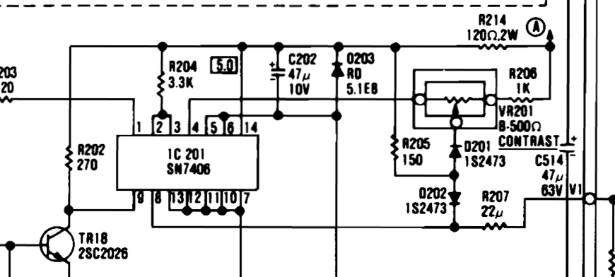
The damaged part candidates could be R214, C202, the transistor TR18, the IC201 or the zener diode D0203. I pulled each one in this order and found that it was the zener diode which was shorting to GND. Of course the last device I test..
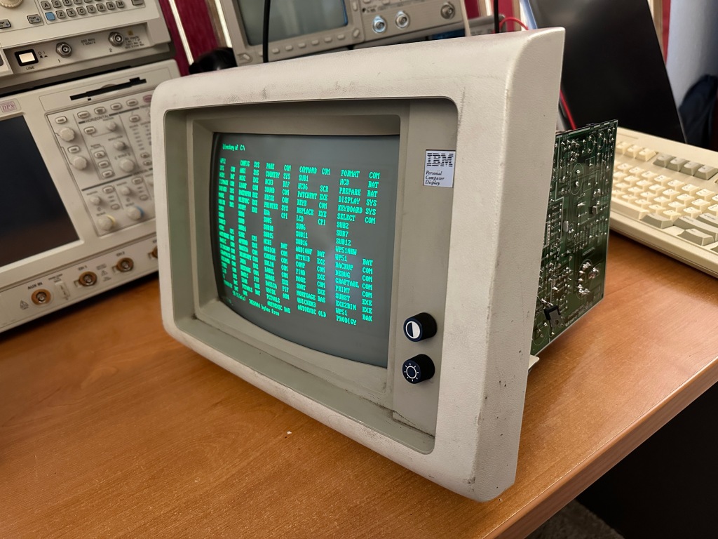
To confirm the theory that the missing 5V was the only issue with the display I sourced this voltage with a bench supply. Thankfully the display began to work!
I had two options: One was to simply replace the diode but I would have to wait a few days/weeks until the delivery arrived, and the other was to replace this circuit with an LM7805 which is a 5V linear regulator which I could harvest from my parts bin – today!
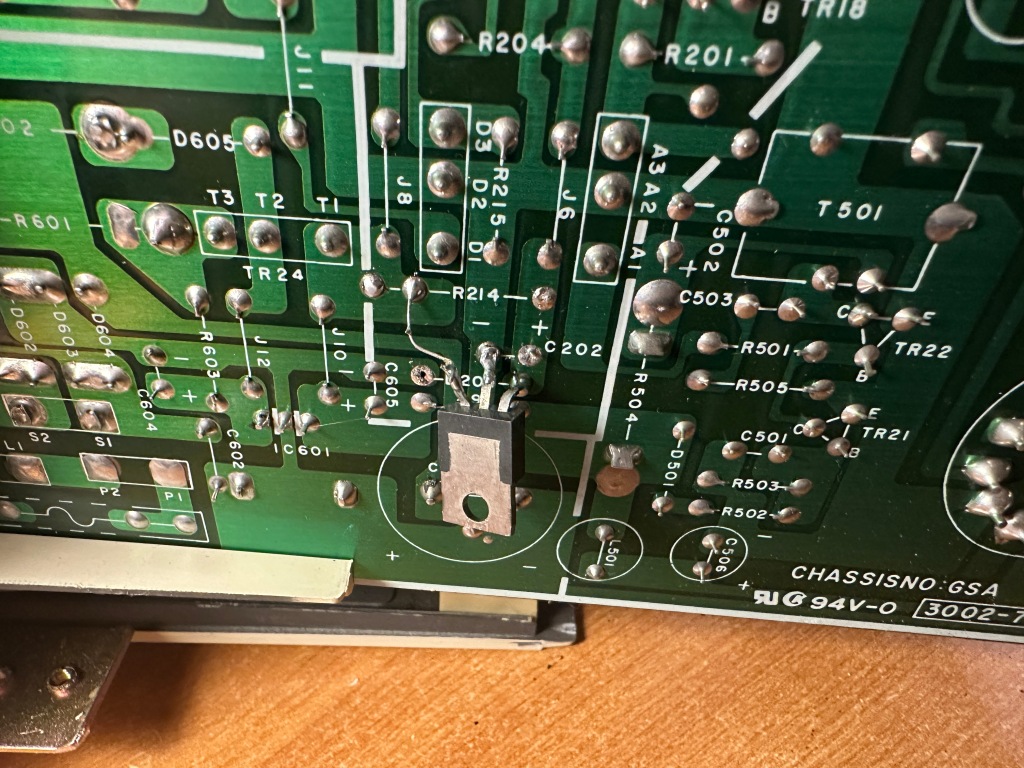
So this is what I did. I removed the resistor R214 and connected the linear regulator’s input to the 14V at R214’s pad.
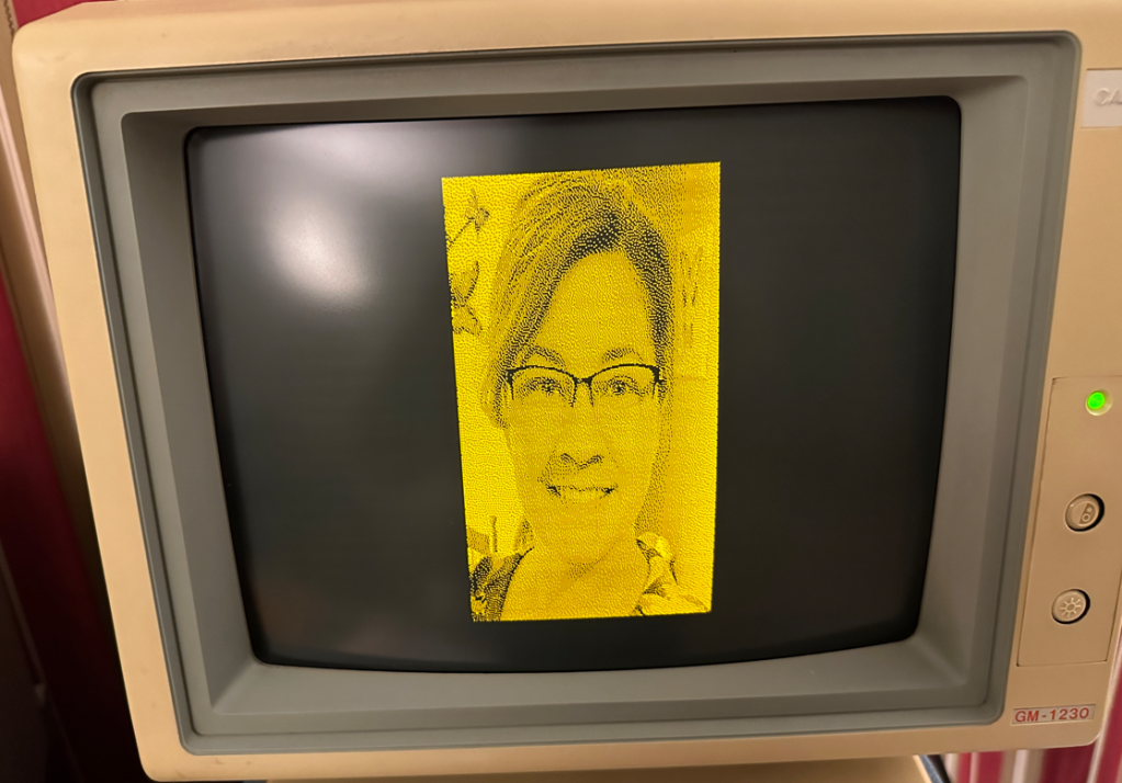
This solution worked great!. Here you can see the display working with the regulator mounted on the bottom-side of the PCB.
After making a few adjustments to the internal POTs it was ready to put back together and give a good scrubbing with a Magic Eraser.